Trim Tabs & Wheel Pants
Below is the aileron trim tab. It
is adjustable by loosening the wing nut and sliding the wire pushrod.
The wire is a looped oval, and passes under a flat washer and
wing nut. The wing nut is secured by a safety ring & clip
looped through the wire. The trim tab is not rigidly attached
to the trailing edge but is hinged with large RC model airplane
nylon hinges to eliminate stress on the Lexan. The wire pushrod,
nylon clevis, and control horn are all RC model airplane items.
There is a 1/4" aluminum tube riveted to the tab to keep
it from twisting. The tab gets adjusted down for flying solo,
and adjusted up level when carrying a passenger. But if you forget,
it is just a minor nuisance for that flight.
.JPG)
.JPG)
.JPG)
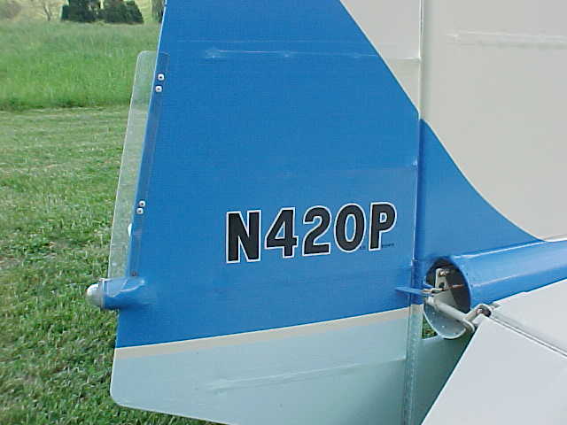
Below left is the rudder tab. It is fixed, &
about two rib bays long. The attaching rivets do not go into the
trailing edge, but into the curved rear portions of the ribs,
where they attach to the trailing edge. Just below the trim tab
is the rear nav light. BAD MISTAKE. Put it somewhere else. Excess
weight on the trailing edge of a MKIII rudder will cause rudder
flutter when you relax pressure on the rudder pedals, which will
then cause you to need a rudder counterweight, on the right.
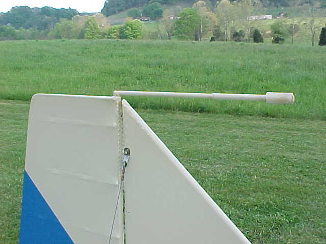
My fix was to make up a counterbalance from a 19"
long 1/2" 4130 tube welded to the top of a 3/4" 4130
tube which fits down into the front rudder spar. The front half
of the counterbalance was made from available scrap, including
iron (heavy) water pipe. Added oversleeves of pipe until the wobblies
went away. Since the rudder on 20P was non standard & squared
off, (like the rest of the MKIII) the task was simplified. If
the rudder had had the standard curved top, adding the counterbalance
would have been more challenging. I suspect the ideal way to balance
the rudder would be after painting it, but before installation
on the aircraft. Then you could lay it over sideways, arrange
to pivot it on the hinge pin, and adjust the rod weight until
it became level.
If you have never seen how wheel pants get mounted
to the landing gear, it's pretty easy. My method is not at all
original, I learned it out of Tony Bingelis' book; "The Sportplane
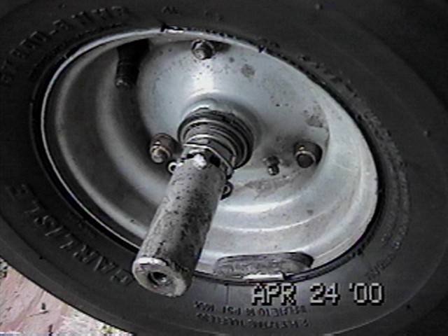
Builder", an excellent resource. The picture to the left
shows how to modify the axle nut: Take a flat washer with a 5/16"
or 3/8" hole and weld an AN-4 nut to the inside. Weld the
washer to a length of 1" steel tubing, and then weld the
tubing to the top of the castellations of the axle nut. (Leave
the slots open for the cotter pin) Weld it true, or the mounting
point moves when the nut is adjusted. The real trick is figuring
how long to make the steel tubing. Mine is 2 3/8" from the
washer face to the outer edge of the castellated axle nut, but
that will vary depending on brakes, non standard wheel bearings,
spacers, type of wheel pant, etc. Note the balance weight: stops
wheel shake just after takeoff.
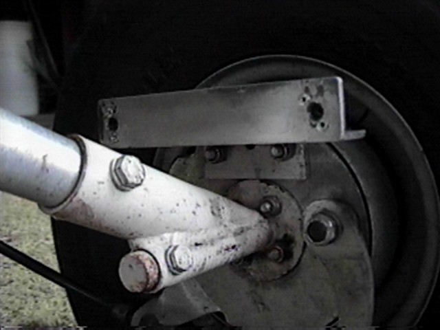
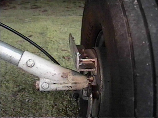 The inside wheel pant bracket is made by taking
two 1" X 1" aluminum angles, overlapping them, and riveting
them together. Then bolt one to the brake backing plate, and the
other gets two AN-3 blind nuts riveted on the wheel side, for
the AN-3 bolts that go through the fender and hold it in place.
Not shown, but a good idea, is adding metal doublers epoxied to
the inside of the wheel pant to reinforce the fiberglass in the
bracket area.
These pictures depict the Kolb aluminum gear legs
and axle brackets. I am no longer using this gear, or wheel pants,
but the basics typically stay the same.
The inside wheel pant bracket is made by taking
two 1" X 1" aluminum angles, overlapping them, and riveting
them together. Then bolt one to the brake backing plate, and the
other gets two AN-3 blind nuts riveted on the wheel side, for
the AN-3 bolts that go through the fender and hold it in place.
Not shown, but a good idea, is adding metal doublers epoxied to
the inside of the wheel pant to reinforce the fiberglass in the
bracket area.
These pictures depict the Kolb aluminum gear legs
and axle brackets. I am no longer using this gear, or wheel pants,
but the basics typically stay the same.