This is the aircraft in it's original configuration.
Since this worked well, it is included, the updated version will
be seen later. The original battery & Kuntzleman Hot Box used
separate platforms of 1/8" aircraft plywood resting on the
frame members on either side of the fuselage under the passenger
seat. They were secured by sewing them in place with rib stitching
thread, and then epoxying over the threads, to the tubing, etc.
Where the threads would have projected above the level of the
plywood and been chafed by the hardware, the plywood was countersunk
and dished out with a Dremel tool. The handle for the BRS parachute
is located on the front tube of the passenger seat frame convenient
to the left hand. The parachute is not currently used.
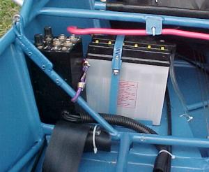
The battery is held in place with a couple small
aluminum angle pieces along the bottom, and a long hose clamp
bolted to the plywood. With a little careful juggling of space,
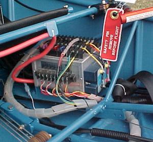
it was also possible to get the intercom to fit into the space
between the battery and the side of the fuselage, and secured
behind the fuselage brace. Note the fuselage brace also supports
the door latch retainer. The intercom is held in place by a little
bungee, which makes it easy to change the 9v batteries.
In flight trim of the elevator was determined to
be a "must-have" item, so here is what we came up with.
Welded a big flat washer to the edge of the original seat frame,
and made a lever also using a large flat washer, with a flat nylon
friction washer between. Then an AN-4 bolt & castellated nut,
nice and snug. Not too hard to move, and stays where you put it.
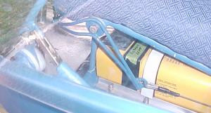
This is also a good time to note where we put the
ELT. It rests up against the cross member, so it's not going anywhere,
yet removing the seat makes it easy to remove the ELT, since it
has microphone capability.
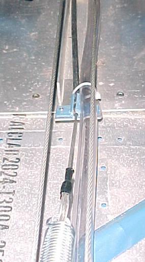
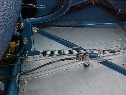
As you lift up on the front of the trim lever, it
tightens the cable, which runs through a standard throttle type
cable sheath and comes out at the rear edge of the middle of the
front floor board through the fitting seen here:
We use a length of aluminum angle running fore and
aft along the floorboard sheet where the rudder pedals are located.
The front edge of it turns up and provides an anchor for the rudder
return springs. (Hated the idea of attaching them to the inside
of the nose cone) The cable retainer for the trim is at the aft
end of the angle, and the clear tube is part of the vacuum venturi
system.
Below is how it attaches to the stick assembly.
Welded up a little bracket to attach to the stick bracket, it
gets the trim pull spring where it needs to be so the leverage
will work right. Below the spring is the radio antenna base, (going
through it's ground plane) and the vacuum venturi tube. Notice
the handle end of the trim lever in the upper left corner. The
antenna does not work well here.
Also note the curved control stick, to fit the modified
seat. The stick is currently slightly forward.